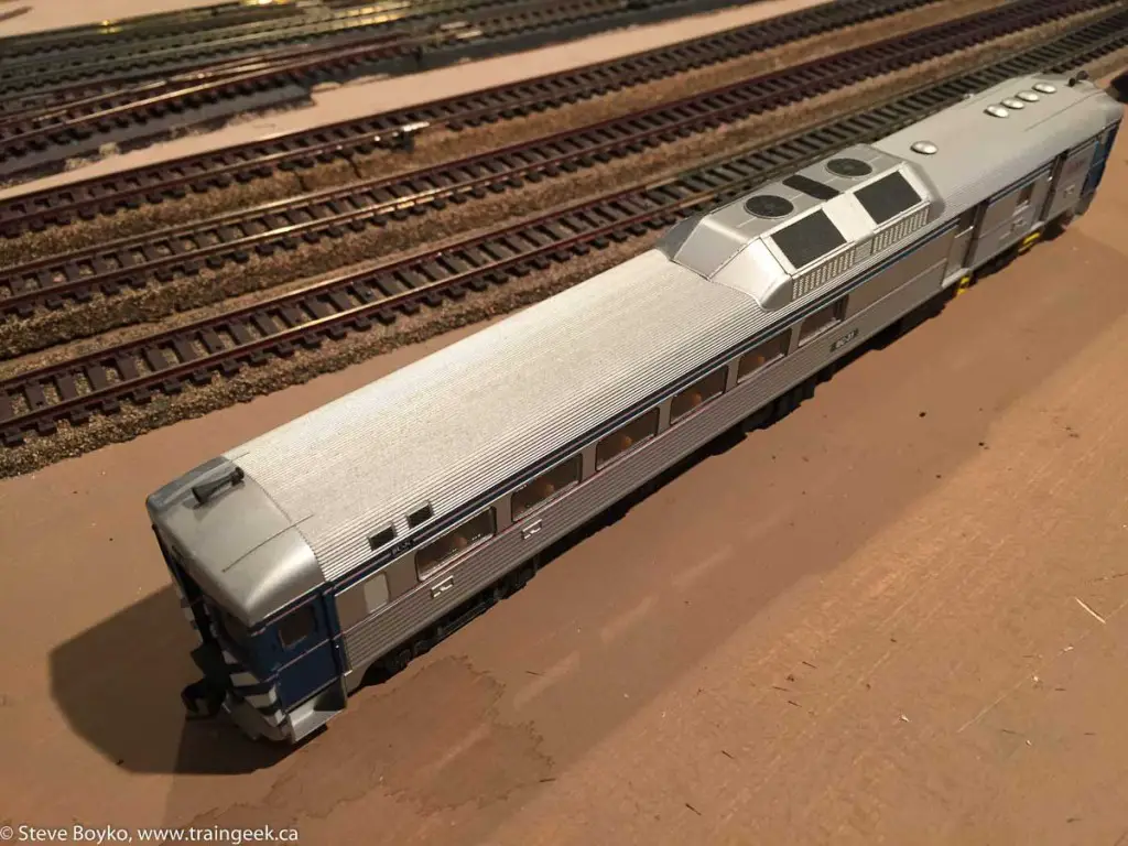
I installed a TCS decoder in a Walthers Proto 1000 RDC today. It was pretty straightforward!
The basic process is as follows:
- Remove the shell (and couplers)
- Cut traces on the board inside
- Solder decoder wiring harness to board
- Tape decoder down
- Replace shell
- Program decoder… and play!
Here are the steps. Just a generic caution – there is a chance you could damage your decoder or your RDC. Be careful and proceed with caution. I’m not responsible if you break something or hurt yourself! 🙂
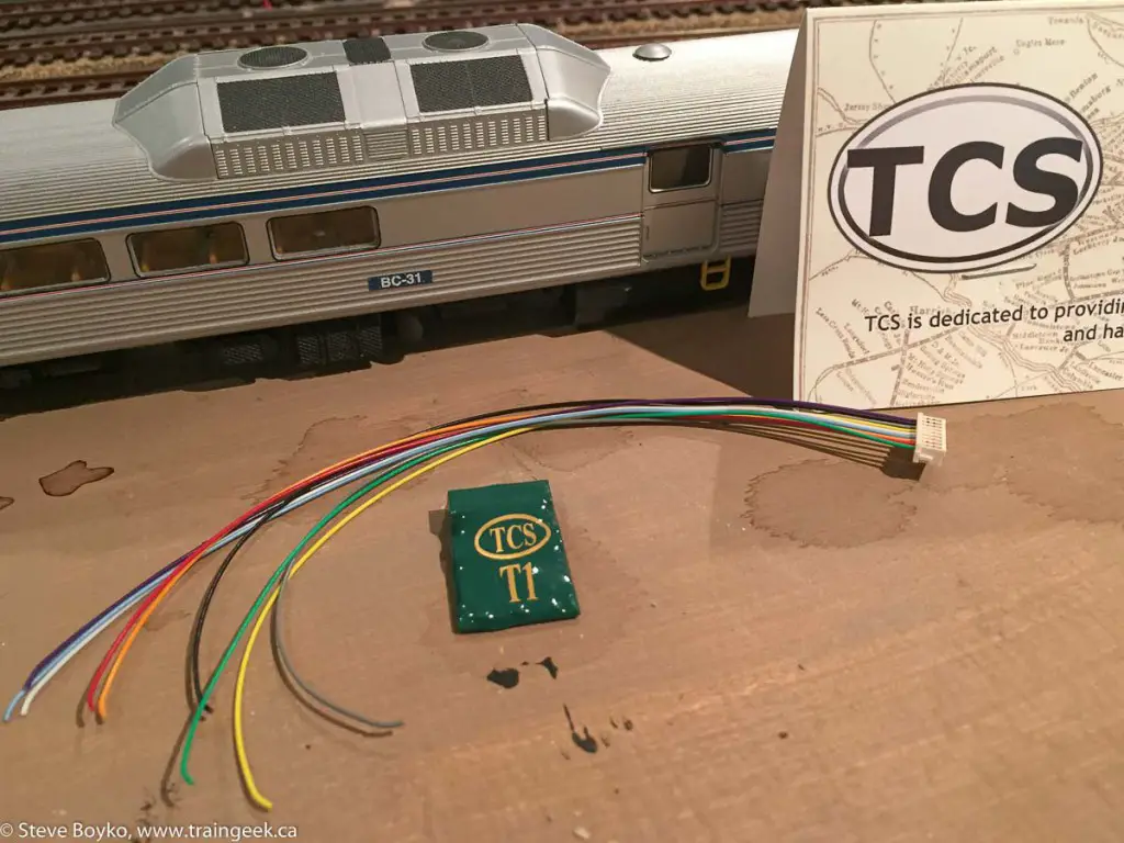
The Decoder
I used a TCS T1 decoder. This is a basic no-frills decoder that comes with a separate wiring harness. The decoder features auto-adjusting BEMF for slow speed control… not really required for a speedy RDC but it came with the decoder anyway.
Removing the Shell
In order to remove the RDC’s shell, you have to remove the couplers on both end, as well as four screws.
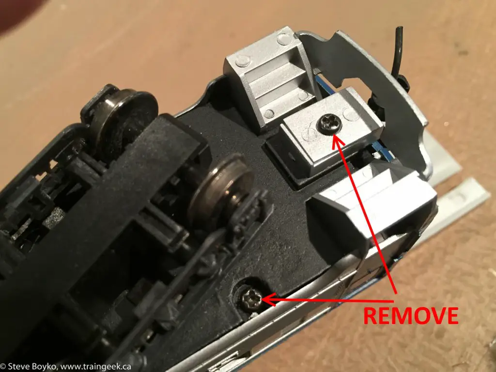
On one end, you have to turn the truck to remove the screws (one per side, as shown in photo above).
The other end is easier as the screws are closer to the end of the RDC.
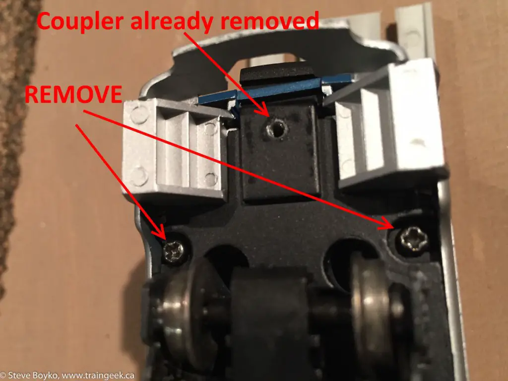
Once all six screws have been removed, the shell slides off pretty easily. It should look like this:
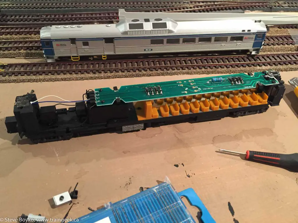
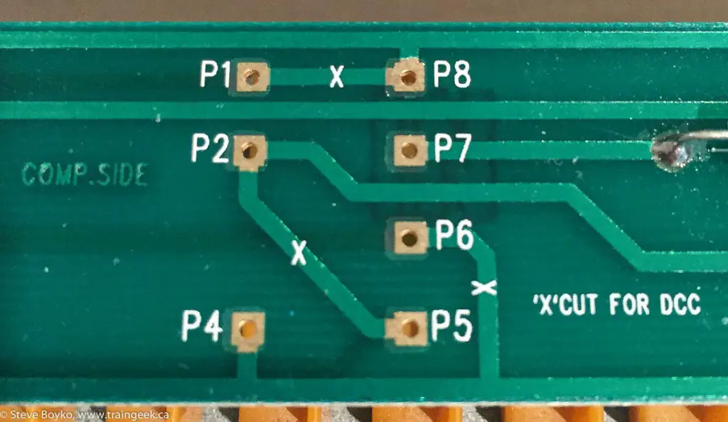
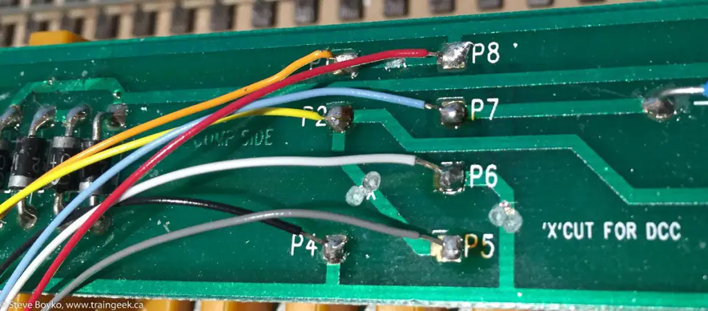
Cut Traces on the Board
There are three traces on the circuit board that need to be cut to enable DCC operation. They are clearly marked with an X.
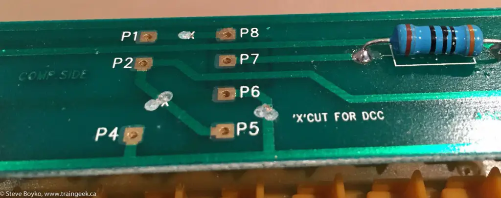
Some instructions say to use a knife to make multiple cuts and eventually break the trace; some suggest using a pin drill to break it. I decided to throw caution to the wind and use a cordless drill.
There are a couple of risks, of course. You could drill right through the board and break a trace on the other side… or you could put too much pressure on the board and snap it. So be careful!
I used gentle pressure, with my free hand on the bottom of the board to support it, and pulsed the drill quickly to remove a bit of material at a time. I found that as long as I was careful to have the drill perfectly perpendicular to the board, it worked very well and the drill bit didn’t wander. A few minutes work and the traces were cut.
Naturally you must test to ensure they are actually cut! I used my ancient digital multimeter to test on each side. You test P2-P5, P1-P8 and P4 to one or the other end of the long trace that runs the length of the board.
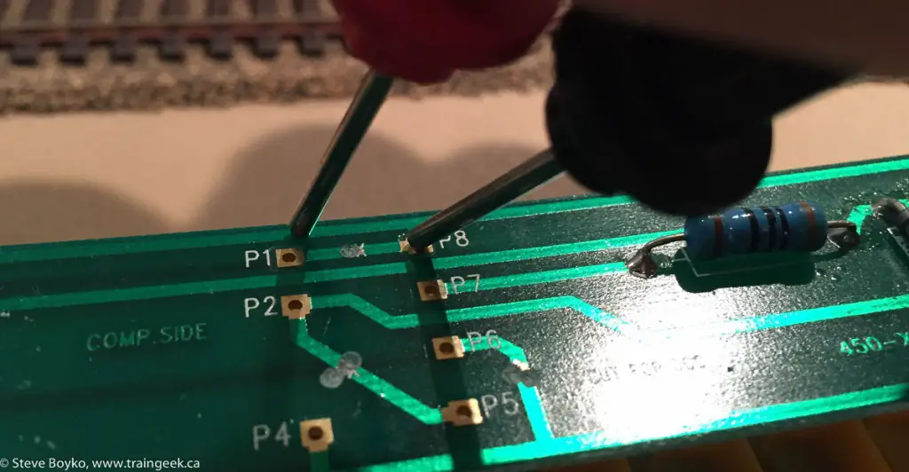
All I was doing was checking to ensure there was no connection between the two points. Simply set your multimeter to measure resistance, and touch the two points. The multimeter should blink or otherwise indicate that it can’t measure resistance, meaning that there is no connection. Make sure you touch the leads together to get a zero resistance reading to confirm that your multimeter is actually working correctly.

My Micronta multimeter blinks “30.00” when there is no connection.
Solder the Wiring Harness
The next step is to solder the wiring harness to the board. DCC wiring harnesses use standard colours so every decoder should have the same meaning assigned to each wire colour. These are the correct colours for this particular board:
- Orange wire (motor positive) to P1
- Yellow wire (rear headlight) to P2
- Black wire (left rail pickup) to P4
- Grey wire (motor positive) to P5
- White wire (front heading) to P6
- Blue wire (common) to P7
- Red wire (right rail pickup) to P8
I did not use green (function F1) or violet (function F2). These could be used for interior lighting, ditch lights etc. if desired.
You may or may not want to cut some of the wire off the harness, as the TCS harness’ wires are quite long. I elected to leave them as is.
Tape Decoder Down
You can’t have the decoder floating around inside the RDC, so you need to secure it somehow. The TCS T1 decoder is already in a sleeve so there is no need to cover it. I stuck a piece of double-sided tape to the circuit board and stuck the decoder to that, then coiled up the wires and used Scotch tape to secure the wires.
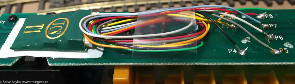
It’s important to not cover the decoder to allow it to dissipate heat.
Replace Shell
Replacing the shell is simple. Slide the shell back on, ensuring that it is oriented correctly – it won’t go on backwards. Make sure you don’t pinch any wires.
Put all six screws back in and you’re ready to program!
You might want to leave the shell off until you confirm the decoder is working
Program the Decoder
You’ll have to refer to your DCC system manual to learn how to program decoders. The TCS T1 comes programmed with address 03 so you will want to change that to something more appropriate, like the number of the RDC itself. In my case the RDC is BC-31 so I programmed it to use 0031.
I had a rising sense of panic when programming this decoder. It wasn’t responding properly and would sometimes show CANNOT READ CV VALUE on my NCE controller, yet I could tell the decoder was responding because it was twitching the motor when I was sending commands. I couldn’t get it to accept the new number…
Finally I realized that the wheels were probably dirty and that was interfering with the decoder receiving the commands. I cleaned them and everything was smooth as silk after that. Lesson learned.
Play
I drove the RDC around for a bit, then coupled up an old Athearn dummy RDC as a trailer and brought it to the CN station in Georgetown.
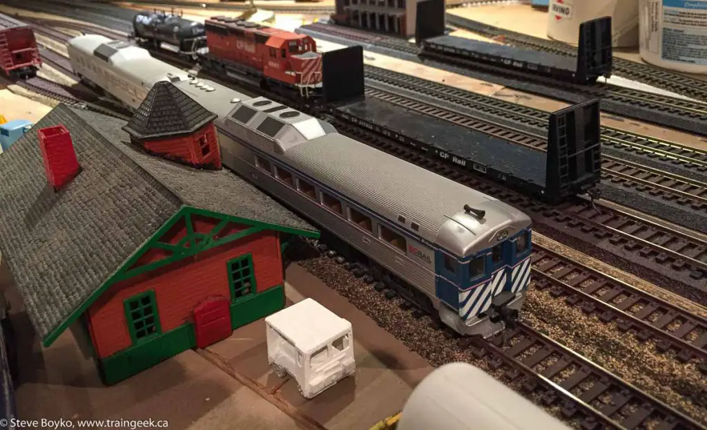
I even took a little video so you can see and hear it run. Note the headlight being turned on at the start.
So that was fun! All told it took about an hour.
For other instructions, you can follow this one from Tony’s Trains which includes replacing the lights with LEDs, or this one from TCS themselves.
PS if you want to wait, you can get Rapido’s new super cool RDC! Check out this great video from Rapido Trains.